|
|
Overview
|
 |
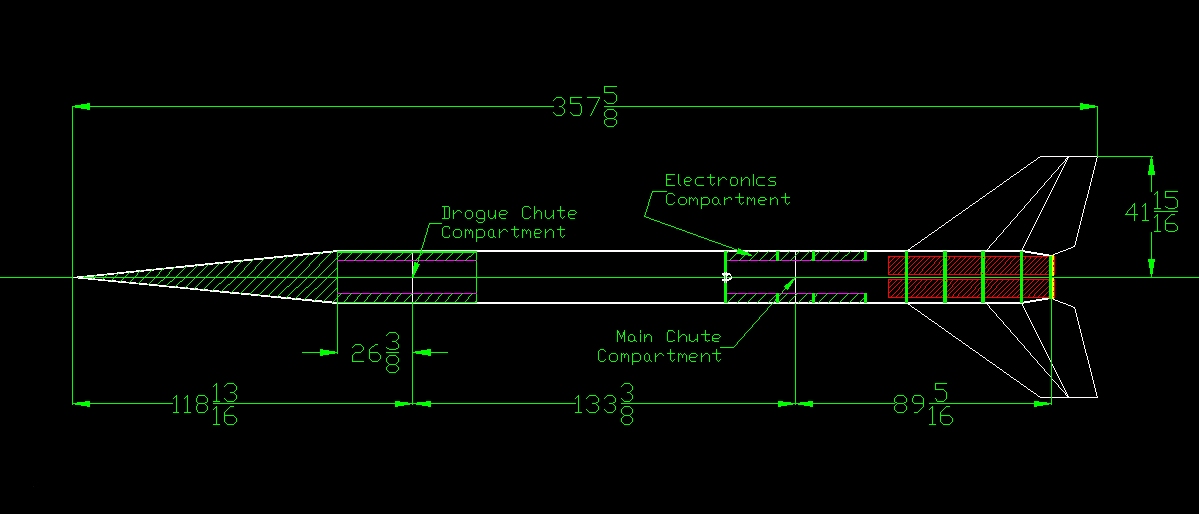
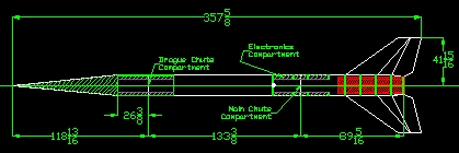
Overall length of 30 feet long with an 18.5"
diameter airframe. |
|
Powered by three 6" "P" motors,
totaling 163,800 Newton-Seconds. |
|
Airframe will consist of three parts, the nose cone,
upper payload section, and the lower booster section. |
|
Recovery will be dual deploy, with a 27 foot drogue
chute, then deploying a 47 foot main parachute. |
|
 |
|
|
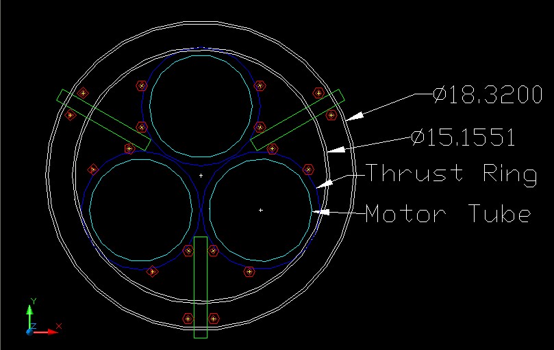
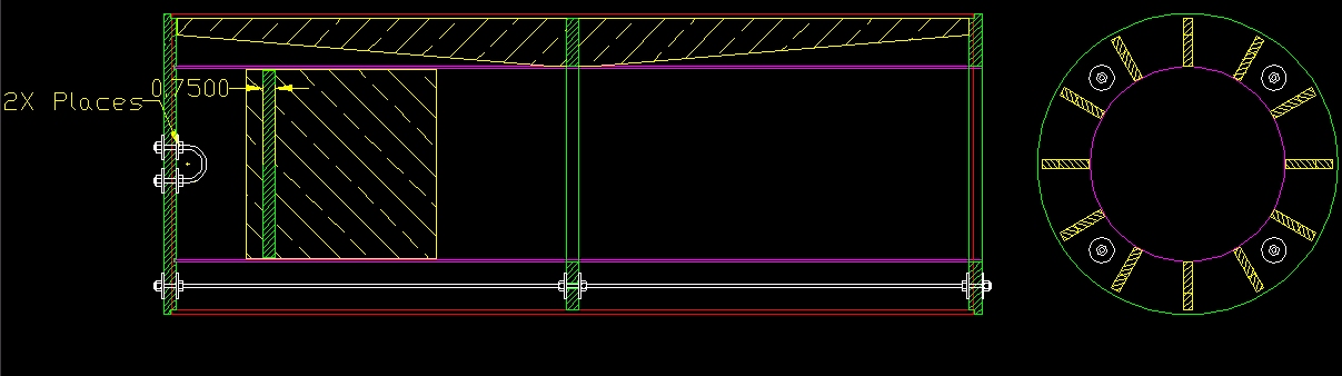
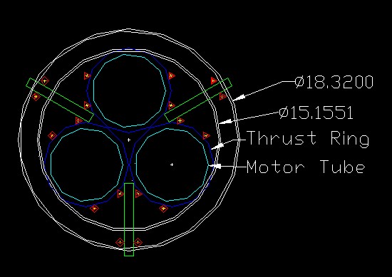
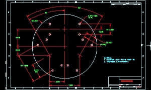
The engine mount will be
an "open frame" design. This design will utilize centering rings
only, and no motor tubes. This is need to prevent heat buildup
within the motor tubes. It will also allow for thermal expansion of the
motors during flight. |
| Currently five centering rings will be
used along the length of the motors, and will be made from 3/4"
birch plywood. |
| The structure of the motor
mount will be maintained by locking the rings in place with both
the fins and several lengths of all thread. |
| There will be a total of 18 pieces of 5/16" all-thread running the length of the motor. |
| There will be be four pieces of all-thread
used for each motor. Two pieces will be
used for motor strength/retention only. The other two pieces will be shared
between motor strength/retention and fin anchoring. Two additional pieces of all
thread will be placed at the body tube to fin tab
junction (see fin description for additional details). |
|
 |
|
| UPDATED 11/28/03 |
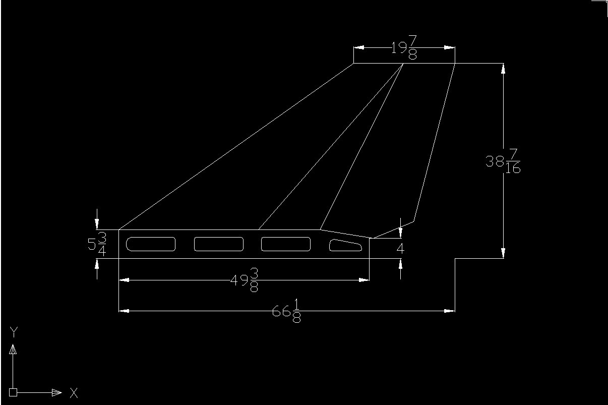
| Current fin design calls for the fins to be cut from
three pieces of 1/4" birch plywood. A full size center section,
along with two backing plates. |
| Once the core material is created, the fins will
be built-up using "Blue Foam" to give them the
scale shape, and then covered in three layers of carbon fiber. |
| For a complete description showing each layer of
the fins check out the fin layer page. |
| Four pieces of all-thread will run the length
of the fin tab. Two pieces will retain the bottom of the tab, and also be shared for motor retention.
Two other pieces will be placed on either side of the fin at the intersection of
the body tube. |
|
 |
|
|
Fiberglass pipe was originally discarded as the
main airframe material due to it's high cost. After doing some
preliminary stress analysis fiberglass pipe is back in the
running. This material is being considered because of the
following criteria:
- High Strength
- Strong recommendation from Neil McGilvray
- Published design data, allowing accurate calculations rather than guess.
- Simpler construction and finishing.
|
|
18 inch diameter "Sonotube" laid up with
three layers of composite (carbon fiber, Kevlar & glass) has
been ruled out. |
|
 |
|
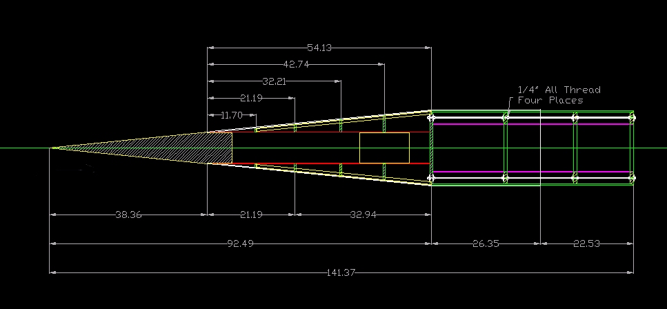
| The nose cone will be built starting with an all
fiberglass section for the tip. This nose cone is being manufactured
and donated to the project by Performance
Rocketry. |
| The central core of the nose will be made from
7.5" PML tube covered in two layers of 10.0 oz glass. |
| Centering rings will be cut from 1/2" birch
plywood. |
| 1/4" plywood ribs will run the length of the
nose cone. |
| The ribs & rings will then be sheeted with
fiberglass strips cut from the airframe material for the first 2/3 of
the nose and PML 11.41" tube strips for the forward most 1/3. |
| A final layer (sealing layer) of glass will then
be applied to the entire nose. |
| The nose cone shoulder will be made in a same
manner as the coupler tubes. |
|
Click HERE for 3D
Solids modeling of the nose cone
|
Coupler Design
|
| Sections of the airframe be cut to form the couplers. |
| Two tube sections will be used for each coupler, with airframe tube
as the outer tube, and glassed 11.41" PML tube for the inner
tube. |
| 1/2" Rib structure will be built between the two tubes. |
| Four pieces of 1/4" all thread will run the length of each
coupler. |
|
 |
Structural Design
|
| Some initial requirements for the strength of the airframe. These
requirements, and the way they were determined are detailed here. |
|
|
|
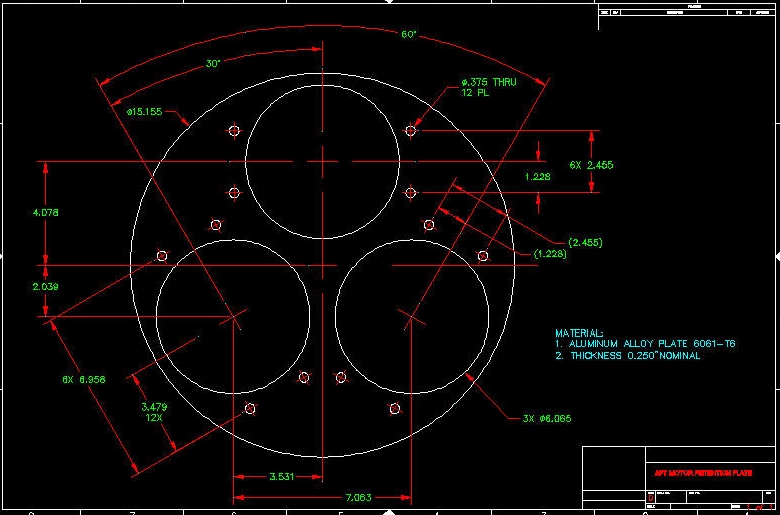
| The forward plate will be the main thrust plate and all thrust should
be centered on that. The four bolt holes per motor will transfer the
thrust from the plate, down the sides of the rocket to each of the
centering rings. |
| Click for AutoCAD Drawing |
|
 |
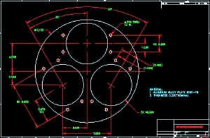
| The aft plate will provide a solid surface for motor retention. |
| Click for AutoCAD Drawing |
|
 |